
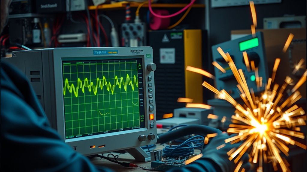
To spot power problems causing ignition noise in your video, look for static spikes or banding synchronized with the engine’s firing or RPM changes. Check for visible arcing on utility poles or flickering overlays that indicate interference. Use a scope or spectrum analyzer to detect periodic spikes matching electrical cycles. Proper grounding, shielded cabling, and adjustable camera settings can reduce noise. Keep exploring for detailed tips on diagnosing and fixing these issues effectively.
Key Takeaways
- Look for evenly spaced static spikes or banding on the video that sync with engine RPM or AC cycle intervals.
- Identify sharp spikes or flickering aligned with 60 Hz power line frequency or engine firing events.
- Check for visible arcing, scorching insulators, or glowing utility poles indicating ongoing electrical faults.
- Use RF receivers or spectrum analyzers to detect broadcast or ignition bursts linked to power line interference.
- Inspect grounding connections, shielding, and cable management to reduce electromagnetic coupling causing video noise.

RV Tire Pressure Monitoring System with 6 Sensors, 6 Tire Positions Monitoring, 0-144 PSI Range, Solar & USB Rechargeable Display, Color Screen for RV, Trailer, Dually Truck and Tow Vehicle
【Real-Time Tire Status Display】Monitor tire pressure and temperature while driving with a wireless tire pressure monitoring system designed...
As an affiliate, we earn on qualifying purchases.
Understanding the Causes of Ignition-Related Video Noise
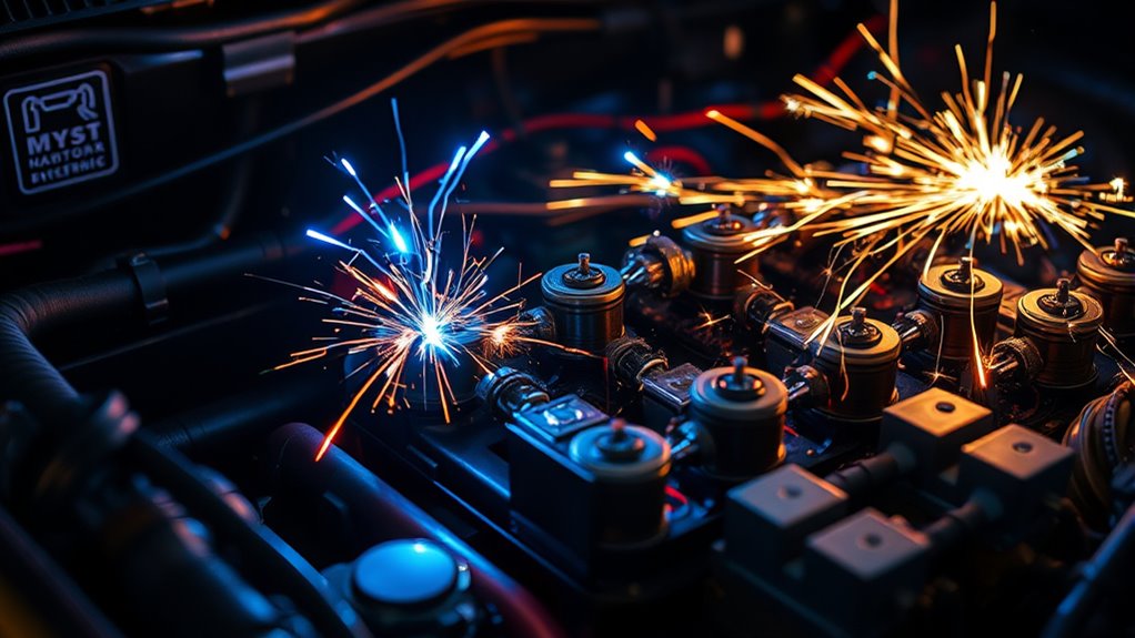
Understanding the causes of ignition-related video noise requires recognizing how various electrical and thermal factors interact with your camera system. Thermal noise originates inside your sensor and amplifier circuits, increasing with higher temperatures, long exposures, or stacking images. This random pixel fluctuation appears as grainy, Gaussian-like noise, especially in low light. Power-supply ripple from your vehicle’s alternator can also introduce periodic interference, creating banding or strobing patterns that sync with engine RPM. Additionally, electromagnetic interference from ignition coils, spark events, and high-current switching can couple into your camera’s electronics and cabling, producing bursts and artifacts. Poor shielding, shared wiring, and ground loops further worsen these effects by allowing RF signals and ground differences to modulate the video signal, resulting in flicker, bands, or streaks. Effective shielding and proper grounding can significantly reduce these ignition-related noise issues. To further mitigate interference, using ground loop isolators and shielded cables can help prevent unwanted coupling from ignition sources. Moreover, implementing filtering techniques such as ferrite beads or electromagnetic interference (EMI) filters can also reduce noise coupling from ignition sources. Ensuring your system has adequate electromagnetic compatibility (EMC) design can help minimize susceptibility to ignition-induced noise. Additionally, choosing components with better thermal management can help reduce thermal noise and improve overall video quality. Incorporating proper cable routing and separation from ignition components can additionally decrease interference and improve video quality.

HXYBBGS 4PCS 86803857 13545366 TPMS Trailer Sensors Compatible with 2020-2025 Chevy Silverado 1500/2500HD/3500HD/ 2021-2025 Tahoe 2020-2025 GMC Sierra 2500HD/3500HD/1500 2021-2025 Yukon
Part Number:86803857, 84152501, 85110397, 13545366
As an affiliate, we earn on qualifying purchases.
Recognizing Visual Indicators of Power Line Interference
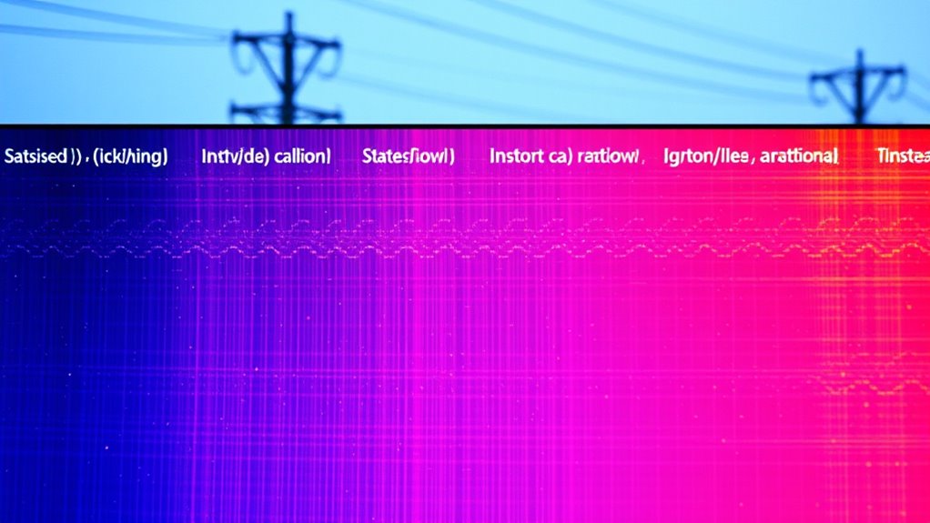
Power line interference often leaves clear visual clues on your video feeds and test equipment. You’ll notice evenly spaced static spikes on band scope displays, with intervals matching the AC cycle—often set at 5 milliseconds per division. Zooming in helps you see these spikes align precisely with vertical divisions, confirming their regularity. Sharp spikes synced to the 60 Hz AC sine wave appear at peaks or half cycles, indicating power line noise. Visible arcing on utility poles, scorching, and glowing insulators over days signal ongoing faults. In video images, static overlays, pixelation, freezing, or blue screens point to interference. Elevated noise floors on ham bands and distorted broadcast signals also reveal power line issues. Recognizing these visual cues helps you identify and troubleshoot power-related video noise effectively. Proper grounding and shielding techniques can significantly reduce the impact of power line interference on your signals. Paying attention to power line maintenance reports and potential equipment faults can help prevent persistent noise problems. Additionally, understanding power line faults and their typical visual signs can aid in quicker diagnosis and resolution. For example, routine filtering of electrical noise can improve signal clarity and reduce the risk of interference affecting your equipment, especially when combined with effective shielding and grounding practices.

Tymate TM2 RV Tire Pressure Monitoring System, Tire Pressure Monitor with Solar Charge, TPMS with 4 Sensors(Max. 10) & 6 Alarm Modes, New Updated w/Color LCD Display, 0-87PSI for RV/Trailer/Truck/SUV
[Discover Five Alarm Modes and Simple Setup for Alarm Thresholds]: With the Tymate Tire Pressure Monitoring System TM2,...
As an affiliate, we earn on qualifying purchases.
Tracking Noise Patterns and Correlations With Engine Activity
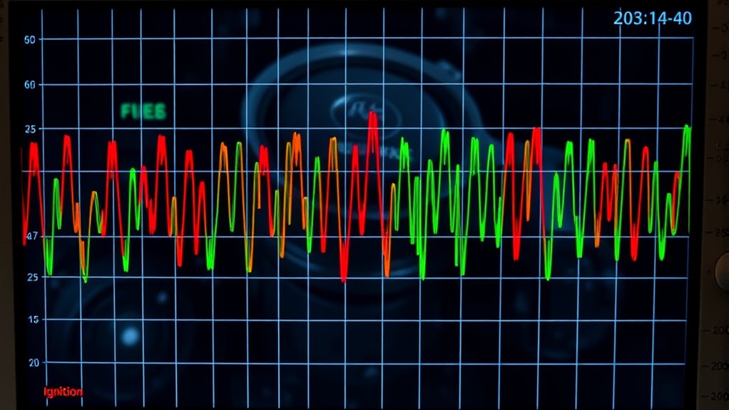
Tracking noise patterns and their correlation with engine activity involves analyzing audio signals to identify ignition-related transient events and their temporal relationships. You should use high-resolution audio (≥48 kHz) to capture ignition transient details accurately. Applying short-time Fourier transform (STFT) or wavelet transform (CWT) reveals recurring ignition bursts and harmonic content. Detect ignition onsets by spotting rapid energy spikes in the 200 Hz–5 kHz range. Computing inter-event intervals (IEI) uncovers firing order, misfires, or skipped events. Cross-correlation with engine reference sensors aligns ignition events with mechanical cycles. This process enables you to monitor energy variations, spectral signatures, and stability across cycles, helping you detect power inconsistencies or deterioration. Regular analysis of ignition timing can improve engine efficiency and reduce emissions. Additionally, understanding Youngster Choice can provide insights into various factors influencing engine performance and diagnostics. Recognizing digital asset management strategies can also support data integrity in engine monitoring systems. Being aware of essential oils for engine health might offer some innovative perspectives on maintenance. Furthermore, integrating advanced diagnostic techniques can enhance the accuracy of engine health assessments.

Tymate TM7 Tire Pressure Monitoring System, Wireless TPMS with 4 External Sensors & 6 Alarm Modes, Colorful Display, Real-time Tire Pressure Monitor System, Ideal for RV SUV MPV Truck Sedan(0-144 PSI)
[Accurate Real-time Monitoring & Multi-Alert System]: Tymate TM7 tpms sensor can be used to monitor your tires’ pressure...
As an affiliate, we earn on qualifying purchases.
Diagnostic Techniques for Isolating Power and Ignition Sources
Effective diagnosis of ignition and power-related noise requires careful setup and targeted measurement techniques. Start by using a battery-powered or isolated oscilloscope to capture ignition waveforms and RF transients without ground-loop interference, as ground connection choices can dramatically alter noise levels. Employ a broadband RF or portable AM receiver to detect radiated ignition bursts and map their spatial origin around the engine bay. Use differential probes or isolation transformers when measuring sensor or ECU signals to prevent ground-related noise paths. Parallel testing with a mechanic’s stethoscope and directional audio probes helps rule out mechanical noises. Additionally, prepare baseline recordings with the engine off, key on, and at various RPMs to compare against live data, aiding in pinpointing noise sources effectively. Understanding the importance of proper measurement tools ensures more accurate diagnosis and effective troubleshooting of power issues. Incorporating proper grounding techniques can significantly reduce measurement errors and improve diagnostic accuracy. Additionally, being familiar with Free Floating concepts can help identify issues related to ungrounded or floating signals that might contribute to noise. Recognizing ground loops early in the process can prevent misdiagnosis and ensure cleaner signal measurements.
Practical Methods to Reduce and Mitigate Video Interference

Reducing video interference caused by ignition noise involves implementing practical shielding and grounding strategies. You should use continuous conductive enclosures, like Faraday cages, to block radiated spikes, and implement single-point star grounding to prevent ground loops that turn transient currents into noise. Adding low-inductance straps between chassis, shields, and ground lowers high-frequency impedance, while ferrite beads on cables attenuate MHz–GHz conducted noise. Use conductive gaskets and filtered connectors at enclosures to seal leakage paths. Consider this visualization:
| Shielding Method | Grounding Technique | Cable Management |
|---|---|---|
| Faraday cages | Single-point star | Separate power and video |
| Conductive gaskets | Proper bonding | Shorten cables |
| Ferrite beads | Low-impedance bonds | Use shielded cables |
| Filtered connectors | Earth grounding | Avoid loops |
Implementing proper grounding techniques is essential for minimizing interference and ensuring video clarity. Additionally, verifying ground continuity with a multimeter can help identify potential issues before they affect signal quality. To further reduce noise, consider shielding cables with additional insulation or wrapping to block external electromagnetic interference. Using grounding straps can also help improve overall electrical stability and reduce noise pathways. Employing grounding techniques that reduce high-frequency impedance is particularly beneficial for maintaining consistent video signal integrity.
Camera Settings and Workflow Adjustments to Minimize Noise
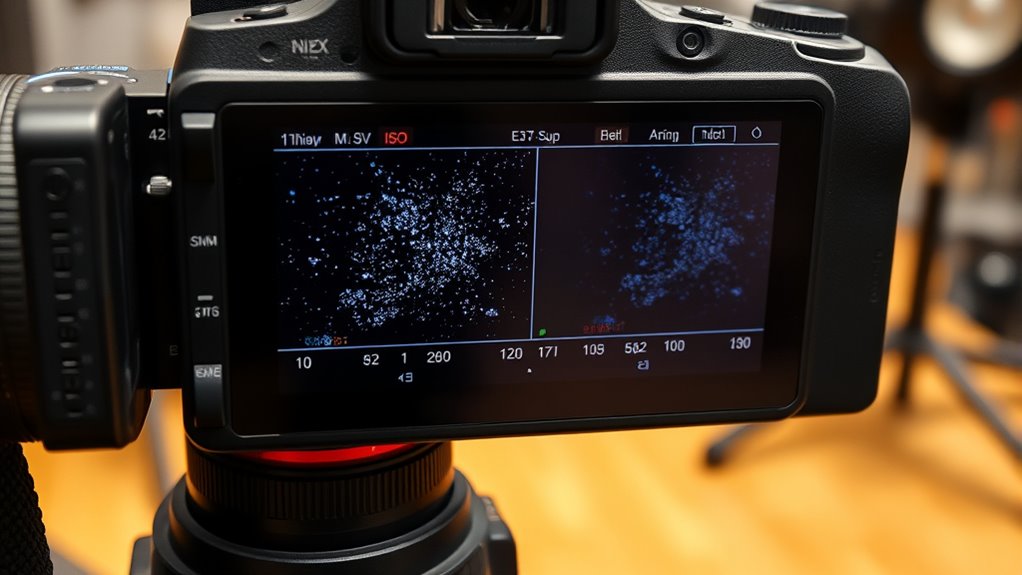
Adjusting your camera settings thoughtfully can considerably minimize noise in your footage. Start by setting your ISO to the lowest native value to optimize the signal-to-noise ratio, and avoid extended ISO ranges that introduce more noise. Use a wider aperture to let in more light, lowering the need for high ISO, and slow shutter speeds to gather additional light without increasing noise—especially useful in low-light scenes. Properly expose your shot by metering at base ISO and applying slight positive exposure compensation to prevent underexposure that amplifies noise. Disable in-camera noise reduction for RAW video to retain maximum detail for post-processing. Additionally, adding artificial lighting before increasing ISO helps improve signal strength, reducing the necessity for high gain. Proper exposure and equipment choices are essential for noise reduction These workflow adjustments help maintain image quality while minimizing noise. Moreover, understanding how attention to detail in camera setup can make a significant difference in noise control can further improve your footage quality. Ensuring your lens quality and maintenance is also crucial, as clean and well-maintained lenses contribute to clearer images with less noise.
Monitoring and Maintaining Electrical System Health

To keep ignition noise under control, you need to regularly check your voltage stability and guarantee your power supplies remain consistent. Inspect your grounding connections thoroughly to prevent interference and maintain system integrity. Additionally, monitoring RF emissions helps identify issues early, reducing potential disruptions and equipment damage. Proper shielding of cables and components also plays a critical role in minimizing electromagnetic interference and ensuring reliable system performance. Regularly assessing electromagnetic compatibility helps prevent unforeseen issues caused by environmental factors. Ensuring proper power supply management can further enhance system stability and reduce the risk of power-related problems. Maintaining system grounding is essential for optimal performance and safety, especially when considering the impact of electromagnetic interference on sensitive electronic components.
Voltage Stability Checks
How can you guarantee your electrical system remains stable and reliable under varying load conditions? Regular voltage stability checks are essential. They help detect issues early and prevent power disturbances that cause ignition noise. Here’s what you should focus on:
- Use supervisor ICs to continuously monitor system health, ensuring voltages stay within safe limits. These supervisor ICs provide high-precision and fast response time, enabling early fault detection.
- Implement visual indicators like rated voltage monitoring LEDs for quick, on-the-spot verification during setup or troubleshooting.
- Conduct thermal monitoring to spot temperature anomalies indicating loose connections or overheating components.
- Employ advanced tools such as P-V curves and PMUs to analyze voltage stability dynamically, revealing potential transient issues before they impact performance.
These measures keep your power system steady and your video equipment noise-free.
Grounding Integrity Inspection
Maintaining grounding integrity is essential for ensuring your electrical system operates safely and reliably. Regular visual inspections help you spot wear, corrosion, or damage on grounding conductors, connectors, and electrodes like rods or plates. Check all connections for security and signs of corrosion, both above and below ground, without excavation. Conduct continuity tests to verify low-resistance paths between ground points using DC or AC methods, ensuring proper bonding and fault current flow. Utilize non-invasive techniques, such as measuring soil resistivity and electrode resistance, to assess grounding health without shutting down systems. Perform routine maintenance by cleaning and tightening connections to prevent resistance build-up. These testing methods are supported by industry standards like IEEE and NEC, safeguarding against shocks, fires, and equipment damage caused by poor grounding or voltage differentials.
RF Emissions Monitoring
Have you ever considered how RF emissions monitoring plays a crucial role in keeping your electrical systems safe and reliable? It helps detect interference, prevent failures, and guarantee compliance with regulations. By using advanced systems like the EPRI RF Monitoring Suite, you gain real-time insights into asset health through wireless sensors on transmission lines, transformers, and structures. These sensors measure parameters linked to failure modes, with embedded algorithms translating data into actionable alerts. Portable and stationary monitors track RF levels over time, providing high, low, and average readings near sensitive sites. Spectrum analyzers analyze signals for interference, harmonics, and transient events. Finally, RF emissions testing ensures electromagnetic compatibility, avoiding disruptions in critical systems and maintaining safety standards.
Frequently Asked Questions
Can Replacing the Alternator Eliminate Video Noise Completely?
Replacing the alternator can eliminate video noise if it’s the faulty source, but it might not solve all issues. You need to verify the alternator is causing the problem by testing it first. Sometimes, other factors like poor grounding, voltage drops, or interference from power lines also contribute. So, while a new alternator helps, consider upgrading wiring, adding filters, and improving grounding to fully eliminate video noise.
What Is the Best Shielded Cable Type for Reducing Interference?
Think of shielding as a fortress protecting your signals; the best type is S/FTP. It combines braided and foil shields, like layered walls, blocking nearly all interference. I once installed S/FTP in a noisy industrial setting, and the difference was striking—video was crystal clear. This shielding provides the highest EMI protection, making it ideal for high-data, interference-heavy environments, ensuring your video stays clean and reliable.
How Often Should Vehicle Electrical Systems Be Inspected for Noise Issues?
You should inspect your vehicle’s electrical systems at least twice a year to catch noise issues early. If you drive in extreme climates or have a high-mileage vehicle, consider inspecting more frequently—every 3 to 4 months. Keep an eye out for signs like flickering lights, dashboard warnings, or strange smells, which signal you need an immediate check. Regular inspections help prevent electrical problems and make certain your vehicle runs smoothly.
Are Certain Camera Models More Resistant to Ignition-Related Noise?
Certain camera models are more resistant to ignition-related noise, especially ISO-invariant full-frame and crop-sensor cameras like the Fuji X-T1, Sony a7R II, and Sony a6000. These models handle long exposures at high ISO better, resisting noise caused by electrical interference from ignition systems. You’ll notice less discoloration and grain, making them ideal for capturing clear images in environments with potential power disturbances.
Can Software Noise Reduction Fully Correct Power-Induced Video Artifacts?
Software noise reduction can’t fully correct power-induced video artifacts. You might reduce some grain and pattern noise, but structured power issues often resist these tools. Aggressive settings can cause blurring or loss of detail, especially in complex scenes. To get the best results, combine in-camera techniques, targeted masking, and careful post-processing. Always test different approaches, and remember that preserving raw footage allows better reversion if needed.
Conclusion
By understanding the signs of ignition noise, you can spot power problems in your video like a detective decoding a mysterious signal. Keep an eye on visual cues, track noise patterns, and use diagnostic techniques to isolate issues. With some practical adjustments and regular electrical checks, you’ll clear the interference like a bright, steady star piercing through a cloudy night, ensuring your footage stays crisp and true.