
To determine if a fuse slot is constant or switched without guessing, use a multimeter or test light to check voltage at the fuse terminals with the vehicle off. If you see battery voltage, it’s a constant circuit. With the ignition on, check again—if voltage appears or changes, it’s a switched circuit. Proper testing and documentation help guarantee accurate identification, so keep exploring for detailed steps and tips.
Key Takeaways
- Measure voltage at the fuse terminals with the vehicle off; constant power shows voltage on both sides, switched power shows voltage on only one.
- Turn the ignition on and off; a circuit that gains voltage only when ignition is on is switched, while constant circuits remain energized.
- Use a multimeter to check for battery voltage (~12.6V) at the fuse terminals; constant circuits typically have continuous voltage regardless of ignition state.
- Test the circuit with a non-contact voltage detector during different vehicle states; constant circuits will show steady voltage, switched circuits will not.
- Cross-reference fuse labels and vehicle diagrams; constant power circuits are often labeled “BATT” and switched circuits “IGN” or “ACC”.

WINAMOO Automotive Test Light with 3-48V LED Digital Voltage Display, Auto Circuit Tester with Voltmeter & Dual Color Polarity Indicate, Electric Test Pen w/Stainless Probe for Car/Truck/SUV Checker
【PRECISE READOUTS & CLEAR DIGITAL DISPLAY】Bright LED display shows highly clear readings in any lighting condition, 0.1V resolution…
As an affiliate, we earn on qualifying purchases.
As an affiliate, we earn on qualifying purchases.
Gather Appropriate Testing Tools and Prepare Safely
Before you start testing fuse slots, gather the right tools and take safety precautions. Wear insulated gloves rated for your vehicle’s voltage, like Class 0 or automotive-rated gloves, to reduce shock risk. Put on safety glasses to protect against sparks or debris when inserting or removing fuse testers. Use a non-contact voltage detector or reliable tester to verify whether a circuit is energized before touching any components, since visual checks can be misleading. Make sure the engine is off, the key is out, and the parking brake is engaged to prevent movement. Use a fuse puller or insulated pliers to remove fuses safely, avoiding metal tools that could cause shorts. Proper safety gear and tools help you work confidently and avoid accidents during testing. Always double-check that the power is disconnected before handling electrical components to prevent shocks or shorts. Additionally, understanding the wave and wind characteristics of electrical signals can help you interpret test results more accurately, since these signals can influence the voltage patterns. Recognizing the difference between constant and switched fuse slots is crucial for diagnosing circuit issues effectively.

6000 Counts True RMS AC/DC Voltage Tester,FS899L Digital Multimeter with Color Screen, USB C Rechargeable Electrical Testing, NCV, Capacitance, Non Contact Voltage Detector for Car, Home(FS899L)
🖥️ 【4.8'' Color Screen & Auto-Ranging】 The FS899L digital multimeter features a large 4.8-inch color display with auto-ranging…
As an affiliate, we earn on qualifying purchases.
As an affiliate, we earn on qualifying purchases.
Understand the Difference Between Constant and Switched Circuits
Understanding the difference between constant and switched circuits is key to proper wiring and troubleshooting. Constant circuits supply power continuously, while switched circuits only energize when the ignition or accessories are on. Testing for voltage at the fuse with your ignition on or off helps identify which type you’re dealing with.
Constant Power Definition
A constant power (CP) supply delivers a steady amount of power regardless of load changes by adjusting voltage and current accordingly. Unlike constant voltage (CV) sources, where the voltage stays fixed, a CP supply varies voltage and current to maintain a set power level. When the load increases, the supply reduces voltage while increasing current; when the load decreases, it raises voltage and cuts current, keeping the power steady. This type of supply is common in specialized applications requiring a consistent power output, even as load conditions shift. It’s different from CV supplies, which prioritize voltage stability, and from constant current sources, which focus on maintaining current. Recognizing whether a power source operates on constant power helps you understand its behavior and how it interacts with connected circuits. Constant power supplies are often used in testing and industrial processes where precise and reliable power delivery is essential. Additionally, understanding the load characteristics can help you determine if a circuit is powered by a constant power source. For example, some power supplies automatically adjust their output based on the load, indicating a constant power operation. Moreover, observing the voltage and current changes during operation can provide clues about whether the circuit is driven by a constant power source.
Switched Power Behavior
Switched power circuits control current flow by toggling connections on and off using devices like relays, transistors, or MOSFETs. This switching allows precise regulation of voltage and current, often at high frequencies (20 kHz–500 kHz), to efficiently manage power with minimal heat. The behavior of switched power depends on duty cycle and frequency, producing an average output that the load perceives as steady. You can identify switched circuits by looking for:
- Voltage only when the ignition or accessories are on
- Intermittent voltage changes during accessory operation or ignition shifts
- Labels like “IGN,” “ACC,” or symbols indicating ignition control
switching frequency can help you determine the type of circuit and its intended function, as different circuits operate at specific ranges. power modulation techniques are used to control the output and improve efficiency, especially in complex electronic systems. Being aware of circuit indicators and their typical behaviors can further assist in diagnosing circuit issues and ensuring proper operation. Additionally, understanding the digital environment at home can aid in troubleshooting and maintaining electronic systems effectively. A solid grasp of analogue and digital signals can also enhance diagnosis of circuit functionality and issues.
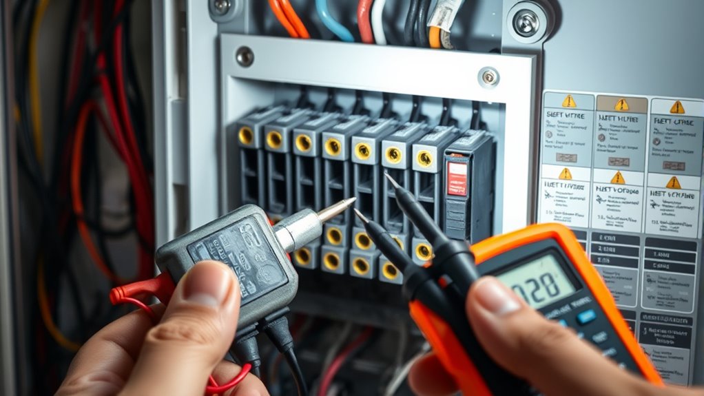
Circuit Testing Techniques
To distinguish between constant and switched circuits, you need to use specific testing techniques that reveal how power flows through the fuse. A circuit tester is effective—connect its ground clip to the negative battery terminal or chassis ground, then turn the vehicle off with the key out of ignition. Probe both exposed metal prongs on the fuse face; if the tester lights on both sides with ignition off, it’s a constant circuit. Turn the ignition on without starting the engine—if only one side lights up, it’s switched. For more accuracy, use a multimeter to check voltage or continuity. Set it to DC voltage or continuity mode, ground the black probe, and test each fuse terminal. Consistent voltage indicates constant power, while voltage only on ignition activation shows a switched circuit. Understanding the electrical wiring terminology can help you interpret your test results more confidently. Additionally, familiarizing yourself with circuit types can improve your troubleshooting precision. Recognizing the power source for each circuit can further aid in diagnosing electrical issues effectively.

Winyxleng Fuse Puller Tool Relay Puller Pliers Fuse Puller Pliers Automotive Tools (6-Pack)
[PERFECT QUALITY]: Our automotive relay puller tool is made of forged metal, designed for strength and durability, 5-packs…
As an affiliate, we earn on qualifying purchases.
As an affiliate, we earn on qualifying purchases.
Identify Fuse Locations and Remove Fuses Carefully

Finding fuse locations requires checking your vehicle’s fuse box diagrams and understanding their typical placements. Interior fuse boxes are usually under the dashboard near the driver’s side or beneath the steering column. Additional boxes can be found in the glovebox or trunk, depending on the make and model. Engine-bay fuse boxes are often near the battery or battery tray, handling high-current fuses. Vehicle-specific manuals and diagrams show the exact number and function of each fuse box. Knowing how to locate these fuse boxes helps prevent accidental damage when removing fuses. To remove fuses carefully: – Use the provided fuse puller or insulated pliers to avoid damage. – Record or photograph the fuse layout before removal. – Inspect the fuse visually through the translucent housing for any signs of damage or burnout. Understanding fuse functions is crucial for proper troubleshooting and maintenance. Additionally, familiarizing yourself with fuse identification can save time and reduce errors during maintenance. Recognizing the fuse type used in your vehicle ensures you select the correct replacement fuse without guesswork. Being aware of visual and auditory cues can also assist in diagnosing fuse issues effectively.

DongChu Insulated Electrician Gloves 1000V,ASTM D120 Certified High Voltage Resistant Flame Retardant Work Gloves, Electrical Rubber Non-slip Prevent Shock,Large
Insulation Performance: Work gloves have insulated palms and fingers and comply with ASTM D120 standard, providing effective safety…
As an affiliate, we earn on qualifying purchases.
As an affiliate, we earn on qualifying purchases.
Test Fuse Slots With the Ignition Off to Find Constant Circuits

To identify constant circuits, use a digital multimeter or test light to check fuse terminals with the ignition off. Probe the metal contacts of each fuse or test points to see if they consistently show around 12 V, indicating a constant power source. Note which slots have voltage, as this helps distinguish between constant and switched circuits for your vehicle’s wiring. A better understanding of automotive electrical systems can help prevent misdiagnosis and ensure proper identification of circuit types. Confirming the voltage presence and understanding circuit wiring principles can help prevent misdiagnosis and ensure proper identification of circuit types. Additionally, familiarizing yourself with fuse box layouts can make testing more straightforward and efficient. Developing a comprehensive wiring diagram can further improve troubleshooting accuracy and speed. Understanding automotive electrical systems is essential for accurate testing and troubleshooting.
Use Multimeter or Test Light
Using a digital multimeter or test light allows you to quickly identify whether a fuse slot is constantly powered or only active when the ignition is on. With the ignition off and the key removed, probe the fuse’s metal contacts. If you see around 12 V, it’s a constant circuit. If the reading is zero volts and then jumps to 12 V after turning the ignition on, it’s a switched circuit. To guarantee accurate results, connect your black lead to a reliable ground like the vehicle’s chassis or battery negative. Remember to recheck your fuse after turning off the ignition to confirm the circuit’s behavior. Testing fuse circuits with a multimeter is more reliable than visual inspection alone. – Use a multimeter for precise voltage readings – Test multiple fuse positions for mapping circuits – Always verify good ground connection. Additionally, understanding the circuit types can help you interpret your readings more accurately.
Probe Fuse Metal Terminals
Examining the metal terminals of a fuse while the ignition is off helps you identify constant circuits. Many modern fuses have exposed metal tabs or small windows designed for probing without removal. These test points let you check for voltage directly at the fuse. Use a low-voltage probe and a known good chassis ground to avoid false readings. Probe both sides of the fuse and compare voltage; if one terminal shows battery voltage and the other reads zero, it’s likely a constant feed. Repeating this across multiple fuses helps identify shared constant buses. Remember, if both terminals show voltage with ignition off, the circuit may be permanently powered. Always verify your readings with a multimeter or test light before proceeding. Proper testing helps prevent misdiagnosis and ensures safety during your electrical checks. Additionally, understanding the electrical system layout can assist in interpreting your findings more accurately. Knowing how fuse circuits are wired can provide context for your testing results and improve troubleshooting efficiency. Being familiar with circuit schematics further enhances your ability to pinpoint the source of power and avoid unnecessary replacements. Gaining a clear understanding of fuse types and functions improves your overall troubleshooting accuracy. Recognizing modern fuse designs can also simplify the testing process and reduce the need for fuse removal.
Note Voltage Presence
Ever wonder how to identify constant circuits in your vehicle? The key is noting voltage presence with the ignition off. Measure voltage at fuse terminals using your multimeter set to DC volts, grounding to the chassis or battery negative. Look for these signals:
- Battery voltage on one or both terminals indicates a constant circuit.
- Zero volts suggests a switched circuit that turns on with ignition or accessories.
- Comparing readings to a healthy battery (~12.6 V) helps confirm full power versus low voltage.
- Always verify the circuit type with a multimeter and appropriate testing procedures.
Re-Test Fuse Slots With the Ignition On or in Accessories Mode

Have you ever wondered if a fuse slot is switched or constant? To test this, turn the ignition to the on position without starting the engine. Keep the engine off and key removed initially for baseline testing. Ground your circuit tester or multimeter to a metal point on the chassis. Remove the fuse box cover for access. Probe both metal prongs on the fuse face. If the fuse lights up or shows around 12 volts, it indicates a switched power source. Re-test by turning the ignition off, removing the key, and probing again to confirm the fuse returns to a cold state. Repeat across multiple slots to ensure accuracy. Using this method helps you identify which fuses are controlled by the ignition or accessories without guesswork.
Verify Circuit Behavior Over Multiple Vehicle States and Time Periods

To accurately determine whether a fuse slot is constant or switched, you need to verify its behavior across different vehicle states and time periods. This involves measuring voltage at various times and conditions, then recording the results to build a clear picture.
Verify fuse behavior across vehicle states and time to determine if it’s constant or switched.
- Check voltage in Off *Accessory*, *Run*, *Cranking*, and *Idle* states, noting any changes or stability.
- Perform repeated measurements at intervals (e.g., 0s, 5s, 30s, 2min) after switching ignition states to identify delayed or latched circuits.
- Log these readings alongside vehicle activity, such as BCM messages or CAN bus signals, to catch circuits controlled by modules or software.
This process reveals if a fuse slot is constantly powered or switched based on how voltage and current behave over time and different conditions.
Use Proper Grounding Techniques to Ensure Accurate Measurements
Proper grounding techniques are essential for obtaining accurate voltage measurements when testing fuse slots. You should choose bare, unpainted metal surfaces on the chassis or engine block for the lowest contact resistance and reliable continuity. Keep the ground close to the fuse or measurement point to minimize loop resistance and voltage drops. Avoid painted, chrome, rusted, or powder-coated surfaces; scrape to bare metal to reduce contact impedance. Use factory grounding studs or thick metal areas like strut towers, ensuring they’re clean. Select the correct wire gauge—10–12 AWG for higher currents—and crimp terminals properly with corrosion-resistant connectors. Mount ground leads securely, supported, and routed away from heat, moving parts, or sharp edges. Always verify low resistance and perform voltage-drop tests before measuring fuse slots for precise, trustworthy results.
Record and Label Fuse Slot Functionality for Future Reference
Recording and labeling fuse slot functionality guarantees you can quickly identify circuit types and troubleshoot issues later. You should use printed diagrams on fuse box covers, which detail components by slot. Cross-reference these with labels under the fuse box lid or your vehicle manual for accuracy. To confirm reliable records, apply adhesive labels inside the fuse cover that note amperage, circuit type, and color codes. Take photos or scan diagrams for easy digital access, and keep spreadsheets with slot numbers, fuse details, and circuit info. Regularly update records after modifications or repairs. Consider using QR codes linking to digital fuse maps. This organized approach saves time, minimizes confusion, and keeps your fuse system well-documented for future reference. Accurate documentation ensures quick troubleshooting and helps prevent electrical issues from recurring.
Confirm Circuit Types by Cross-Checking With Vehicle Documentation

Cross-checking your fuse box with vehicle documentation is essential for accurately identifying whether a fuse slot is constant or switched. Start by consulting the owner’s manual, which provides factory fuse diagrams indicating circuit types with BATT or IGN labels. Next, review the vehicle’s service or repair manual for wiring diagrams showing power distribution and relay locations, helping you verify if a fuse is battery-fed or ignition-fed. Examine the fuse box covers, which often have maps labeling circuits as “IGN” or “BATT.” Manufacturer bulletins and OEM wiring diagrams offer detailed insights, including wire color codes and pinouts. Comparing this information with your physical fuse box helps confirm circuit types, reducing guesswork and ensuring accurate identification of constant versus switched fuse slots.
Frequently Asked Questions
How Can I Tell if a Fuse Slot Is Constant or Switched Without Removing the Fuse?
To tell if a fuse slot is constant or switched without removing the fuse, you should use a circuit tester or multimeter. Turn the car off and probe both fuse terminals; if the tester lights up or the multimeter shows voltage, it’s a constant fuse. Then, turn the ignition on and check again; if voltage appears only when the ignition is on, it’s a switched fuse.
What if a Fuse Slot Shows Voltage Even When the Ignition Is Off?
Think of your fuse box as a river that flows differently depending on the season. If a fuse shows voltage with the ignition off, you’re observing a constant current, like a river fed by an underground spring. This means that circuit is always active, unaffected by your key’s position. Use a circuit tester to confirm, and remember, some circuits are designed to stay energized all the time—essential for safety and vehicle functions.
Can Empty Fuse Slots Be Used to Identify Switched Circuits?
Yes, you can use empty fuse slots to identify switched circuits. Turn the ignition on and probe both sides of the empty slot with a multimeter. If voltage appears only when the ignition is on, it’s a switched circuit. When the vehicle is off and no voltage is detected, it confirms the slot is switched. Always double-check by turning off the ignition and re-probing for accuracy.
How Do I Distinguish Between Constant and Switched Circuits on Complex Fuse Boxes?
To differentiate between constant and switched circuits in complex fuse boxes, you can gently test each fuse with a multimeter or test light. With the engine off and key out, check for voltage; if present, it’s likely constant. Turn the ignition on and test again; if voltage appears only then, it’s switched. Always consult your vehicle’s fuse diagram for guidance, and proceed carefully to guarantee accurate identification without guesswork.
What Is the Safest Method to Test Fuse Slots Without Risking Damage to Vehicle Electronics?
You should use a multimeter set to DC volts or continuity mode for testing fuse slots safely. Turn off your vehicle, disconnect the battery if possible, and verify your test equipment is functioning correctly. Carefully probe the fuse terminals, avoiding contact with other components. Confirm your ground connection is solid, and always wear safety gear. This approach minimizes risk to your vehicle’s electronics while providing accurate results.
Conclusion
By following these steps, you’ll confidently distinguish between constant and switched fuse slots, much like a seasoned detective piecing together clues. This process not only guarantees safety but also saves you time and frustration down the line. Remember, thorough testing and careful documentation are your best tools — think of them as a map guiding you through the electrical maze of your vehicle. With patience and precision, you’ll master your car’s circuitry like a true professional.