
To avoid “accessory power” confusion, you should understand the different vehicle circuits and use factory wiring diagrams to identify constant, switched, or relay-controlled sources. Verify power sources with a multimeter before connecting your accessories, and choose the correct fuse and fuse tap to match the circuit’s ratings. Using relays for high-current loads and properly labeling all connections keeps things clear. Mastering these steps guarantees safe, reliable installs—continue exploring to get all the details.
Key Takeaways
- Refer to the vehicle’s fuse box legend and wiring diagram to identify circuits labeled as “accessory” or “ACC.”
- Use a multimeter to verify voltage levels at accessory circuits with the ignition in different positions.
- Confirm fuse ratings and descriptions match OEM specifications to prevent misidentification of power sources.
- Label wires and fuses clearly with standardized color codes and documentation for quick identification.
- Disconnect the battery before working on accessory circuits to avoid accidental activation and confusion.
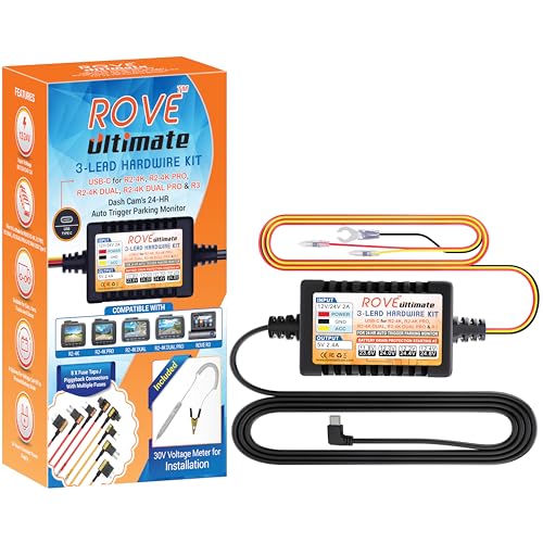
ROVE Ultimate Dash Cam Hardwire Kit with USB-C Port for R2-4K, R2-4K PRO, R2-4K Dual, R2-4K Dual PRO, and R3 Dash Camera Models, 24Hr Parking Monitoring Kit with Low Voltage Protection
【Compatible for ROVE R2-4K with USB-C Port, R2-4K PRO, R2-4K DUAL, R2-4K DUAL PRO, and R3 Dash Cam...
As an affiliate, we earn on qualifying purchases.
Understand the Different Types of Vehicle Power Circuits

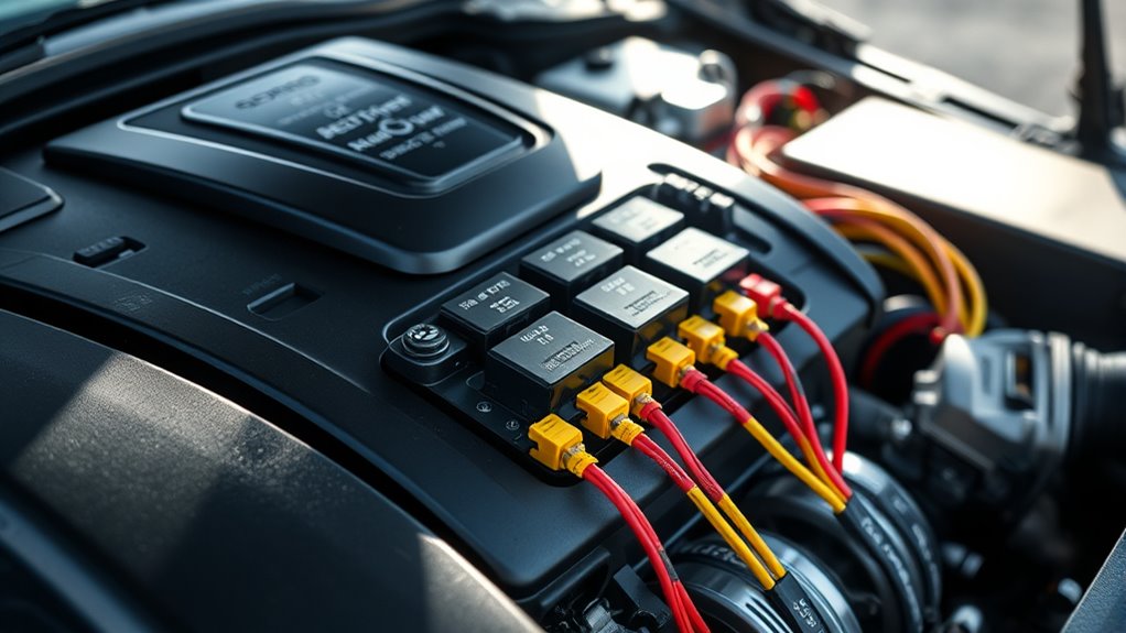
To avoid confusion with accessory power in modern cars, it’s essential to understand the different types of vehicle power circuits. Your vehicle’s power source comes from the battery or alternator, supplying electrical current to various loads like the ECU, fuel pump, or starter motor. The circuit is completed through grounding, either directly to the chassis or via harness terminals. Conductors in wiring harnesses carry current throughout the vehicle, with fuse boxes protecting circuits right after the battery’s positive terminal. Power distribution varies: some circuits are constantly hot, drawing directly from the battery, while others are switched on by the ignition switch’s different positions—such as IGN1, IGN2, or ACC. Starter-only circuits activate during cranking, and relay-switched paths route power through relays, ensuring proper operation. Understanding circuit wiring diagrams is crucial for troubleshooting and proper wiring installation. Additionally, knowing how power management systems regulate and distribute electrical loads can help prevent common wiring issues and ensure reliable vehicle operation. Proper knowledge of circuit types and functions can also assist in diagnosing electrical problems more efficiently. Recognizing the difference between switched and unswitched circuits allows for more accurate troubleshooting and safer modifications. Familiarity with circuit protection devices, such as fuses and circuit breakers, is also important to prevent damage from electrical faults. Moreover, understanding how fault codes and diagnostic tools interact with these circuits can streamline the repair process and reduce diagnostic time.

REDTIGER F7N Dash Cam Hardwire Kit USB C Port, Dashboard Camera Car Charger Cable Kit 12V- 24V to 5V w/Fuse Kit, Low Voltage Protection for Dash Cam Double-4 Fuses
【Wide Compatible】Input:12V-24V; Output:5V/2A. With Type-C ports, this hardwire kit compatible with all of dash cams.
As an affiliate, we earn on qualifying purchases.
Consult Factory Wiring Diagrams and Service Manuals
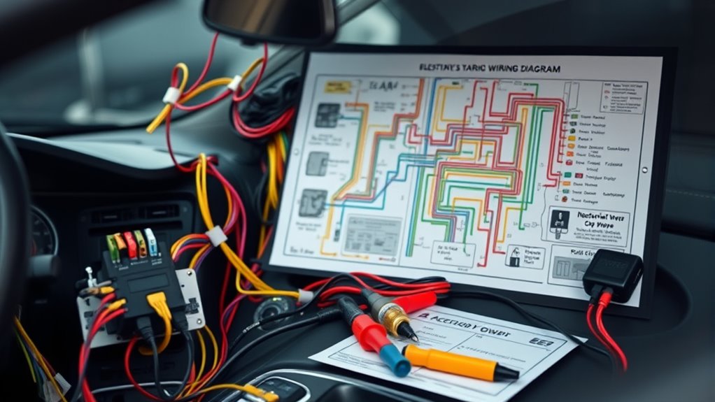
Consult factory wiring diagrams and service manuals to accurately identify circuit types and guarantee mistakes. These resources confirm fuse assignments and show detailed wiring layouts, guiding your connections. Using a multimeter with these diagrams ensures your testing is precise and safe. Additionally, understanding circuit identification helps prevent misinterpretation of wiring schemes.
Identify Circuit Types
Understanding the different circuit types in your vehicle starts with carefully examining factory wiring diagrams and service manuals. Look for labels like “hot at all times” or terminal numbers such as 30 and 15 to identify battery-hot and ignition-switched circuits. Find terminal 50 or START connections to spot starter-switched feeds active only during cranking. Trace alternator output and charging nodes to locate charging-fed circuits that supply power when the engine runs. Use fuse box legends and bus labels to differentiate accessory-bus from fused distribution circuits. Confirm ground points by following negative return paths and chassis-ground symbols. Recognizing these circuit types helps prevent confusion, ensuring you correctly identify power sources and avoid mistakenly attributing accessory power to ground or vice versa. Circuit identification is essential for precise troubleshooting and safe modifications. Additionally, understanding factory wiring standards can further streamline the process and reduce errors during diagnostics, especially when consulting detailed wiring schematics and circuit labels. Paying attention to circuit color codes can also aid in quickly tracing and verifying connections.
Confirm Fuse Assignments
Verifying fuse assignments begins with checking that the actual fuse numbering in your vehicle matches the factory wiring diagram’s index. You need to confirm that labels and numbering on the fuse box align with OEM diagrams, not just quick-reference charts. Use the service manual to read exact fuse descriptions, avoiding ambiguous shorthand. Cross-check high-current fuses in pre‑fuse boxes separately, as they often have different numbering and functions. Note the fuse ratings and types to ensure correct replacements. Also, record any “spare” or “not used” slots listed in the diagram, since some appear active. To deepen your understanding: Always disconnect the battery before servicing high-current fuses to prevent electrical shock. Confirming the fuse assignments helps prevent accessory power issues caused by incorrect fuse identification. 1. Match physical fuse labels with factory descriptions. 2. Verify fuse ratings and types match OEM specs. 3. Cross-reference high-current pre‑fuse box fuses separately. 4. Note unused fuse slots marked as “not used.”
Use Multimeter Verification
Using a multimeter to verify accessory power circuits requires you to follow precise procedures aligned with factory wiring diagrams and service manuals. First, set up your multimeter: insert the black lead into the COM jack and the red lead into the V/Ω jack. Turn the dial to the Ω symbol and select continuity mode. Test the leads together to confirm functionality—listen for a beep indicating proper operation. When testing, ensure the ignition is off and disconnect the battery negative terminal for safety. Use the probes to check for continuity across fuses or switches, and look for a steady beep and low resistance (0.0–0.2 Ω) to confirm good connections. For voltage checks, switch the meter to DC voltage, contact the wire with the red probe, and chassis ground with the black. Verify expected voltages per wiring diagrams. Additionally, understanding circuit diagrams can greatly assist in accurately identifying accessory power sources and troubleshooting issues. To improve accuracy, it’s helpful to familiarize yourself with factory wiring standards, which can vary between vehicle models.

USB-C Hardwire Kit for Dash Cam with Acc Detection, 4-Level Adjustable Low Voltage Protection & Automatic LED Voltmeter, 3-Lead Power Cable for Dash Camera Parking Mode & Continuous Recording
Voltage Step-Down Power Supply: This product is a special pressure drop line for driving data recorder. Through the...
As an affiliate, we earn on qualifying purchases.
Verify Power Source Behavior With a Multimeter
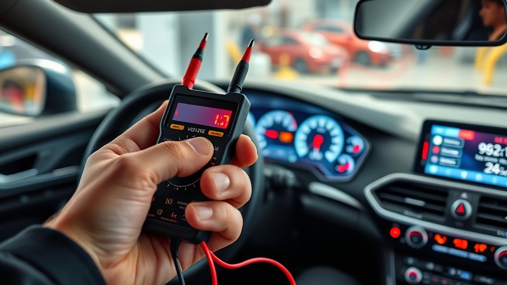
To accurately diagnose your car’s electrical system, you need to verify how the power source behaves with a multimeter. Start by setting your multimeter to 20V DC, insert the black probe into COM, and the red into volts/ohms/milliamps. Before testing, ensure the battery reads between 12.4-12.7V with the engine off, establishing a good baseline. Most car batteries are designed to last around four years, so a healthy reading indicates a well-maintained system. Additionally, understanding automotive electrical fundamentals can help interpret your multimeter readings more effectively, which is essential for identifying power source behavior issues accurately. Recognizing the electrical system’s normal voltage ranges can further assist in diagnosing potential problems early. Next, follow these steps: 1. Ground the black probe to a chassis metal point. 2. Probe the positive terminal or wire with the red probe when the ignition is off, expecting around 12V for constant sources. 3. Turn the key to accessory mode, and verify the voltage rises to about 12V. 4. Confirm no voltage on accessory wires when ignition is off, guaranteeing proper source behavior. 5. Remember that electrical system diagnostics can reveal underlying issues that may not be immediately visible, helping you prevent potential breakdowns. Additionally, being familiar with battery health indicators can further improve your troubleshooting accuracy.

Dash Cam Hardwire Kit USB C, 12V-24V to 5V/3A Adapter Power Cable with Voltage Display, 24/7 Parking Mode, Acc Detection, 4-Level Low Voltage Protection (11.6V/11.9V/12.2V/12.5V)
24/7 Parking Monitor: This power adapter system provides 24/7 parking surveillance, recording incidents like hit-and-runs, vandalism, or theft...
As an affiliate, we earn on qualifying purchases.
Choose the Correct Fuse and Fuse Tap for Your Accessory

To prevent power issues, you need to select the right fuse type and fuse tap for your accessory. Make sure the fuse fits your vehicle’s fuse box and matches the circuit’s voltage and current ratings. Using a proper fuse tap ensures your new connection stays secure and maintains the circuit’s safety. Proper fuse selection also involves considering the fuse’s rated voltage, current, and breaking capacity to ensure it can handle the system’s electrical demands safely. Additionally, understanding fuse ratings helps prevent overloads and potential damage to your vehicle’s electrical system. Being aware of vehicle wiring and compatibility factors can also help you make informed decisions when purchasing necessary accessories or tools. Paying attention to circuit protection principles is essential for avoiding electrical issues and ensuring long-term reliability. Incorporating sound wave influence principles from sound healing science can even inspire more stable and harmonious electrical system setups.
Verify Fuse Circuit Type
Before installing a fuse or fuse tap for your accessory, it’s essential to verify the circuit type to guarantee compatibility. First, consult your vehicle’s manual or fuse box diagram to identify the circuit’s fuse type and rating. Second, inspect the fuse prongs: two for standard blade fuses, three for micro types. Third, measure the fuse’s physical dimensions—mini fuses are smaller, maxi fuses are wider at 29.2mm. Fourth, note the color coding, which indicates amperage across most blade and Bosch fuses. This assures you select the right fuse type, whether mini blade, glass tube, Bosch, or high-current. Proper verification prevents damage, guarantees safety, and confirms your accessory receives the correct power supply. Additionally, understanding the SWIFT/BIC codes associated with your banking transactions can help ensure secure and accurate transfers if you need to fund your accessories or related purchases. To further ensure compatibility, consider reviewing fuse circuit type details specific to your vehicle model. Being aware of the best home security systems and their features can also be helpful if you plan to integrate smart security devices into your vehicle or home. Moreover, verifying the growing importance of glycolic acid benefits can guide you in selecting proper skincare products to complement your vehicle’s maintenance. Confirming the AI applications in learning relevant to automotive diagnostics can also assist in troubleshooting electrical issues effectively.
Use Proper Fuse Tap
Choosing the right fuse tap is essential to guarantee a safe and reliable connection for your accessory. First, match the fuse tap family to your vehicle’s fuse type—whether ATO/ATC, ATM/mini, Low-Profile Mini, Micro2, Micro3, or AGC/round glass—to ensure proper fit and contact. Confirm whether the fuse housing requires one or two prongs, especially with secondary load contacts, to maintain circuit protection. Use taps designed for vacant energized slots if tapping an empty fuse position, avoiding forced fits that could damage the fuse block. For under-dash or engine bay locations, select weatherproof or sealed variants. Always compare the tap’s blade profile with the original fuse, rather than relying solely on common names, to prevent mismatches and ensure safe, secure connections. Proper fuse tap selection helps prevent potential electrical issues and ensures your accessory functions safely and effectively. Additionally, understanding fuse compatibility is crucial to avoid damaging your vehicle’s electrical system.
Match Fuse Rating
Selecting the appropriate fuse rating for your accessory starts with accurately calculating its steady-state current draw. First, determine the continuous current from manufacturer specs or measured amperage during typical use to avoid undersizing. Second, add estimated inrush or startup current for motors or capacitive loads, measured with a clamp meter or from datasheets, rather than relying on steady-state alone. Third, apply a safety margin—about 125% for industrial or automotive loads—and document your rationale. Fourth, compare your current estimate to the circuit’s wire ampacity and vehicle wiring limits; never choose a fuse exceeding these ratings. Fifth, consider the fuse’s response time and type (fast-blow or slow-blow) to match the load characteristics. Finally, re-measure with the engine and accessories on to account for multiple loads, ensuring your fuse can handle actual operating conditions without nuisance blows. Understanding fuse response times is crucial to prevent unnecessary circuit interruptions and ensure reliable protection.
Use Relays for High-Current or Uncertain Power Sources
Using relays for high-current or uncertain power sources guarantees safe and reliable operation in your vehicle’s electrical system. Select relays with contact ratings at least 25–50% higher than your accessory’s expected current to reduce contact wear and ensure safety margins. Match the coil voltage to your vehicle’s 12 V system to prevent coil damage. Use sealed or automotive-rated housings for under-hood or exposed locations to resist moisture, dust, and vibration. For high-current applications, opt for stud or bolt-style relays rated above 80–100 A, or relays with integrated high-current contacts up to 200+ A. Double-throw or dual-pole relays help switch multiple circuits simultaneously, avoiding ghost powering. Properly sized and positioned relays improve system safety, longevity, and performance while minimizing electrical issues. For demanding automotive use, consider high-current relays such as the TE High Current Relay, which is designed to handle up to 130 amps with reliable contact ratings and durable construction.
Properly Label and Document Your Installations

Clear labeling and thorough documentation are essential for guaranteeing your automotive electrical installations remain safe, organized, and easy to troubleshoot. Proper labels should include product specs, handling instructions, part numbers, and manufacturer details, all made with durable, heat, moisture, and chemical-resistant materials. To ensure clarity and compliance, follow these best practices:
Clear labeling and documentation ensure safe, organized, and easily troubleshootable automotive electrical systems.
- Label wires with their functions, such as ACC, negative, or turn signals, using standardized color codes.
- Document fuse box connections, verifying ACC wiring with the engine off and key removed.
- Attach certification labels like UL or SAE standards to identify compliance and safety.
- Record installation details, including voltage ratings, manufacturer info, and heat resistance, for future reference. Durable labels help maintain safety standards throughout the vehicle’s lifecycle, ensuring labels stay legible and intact despite harsh conditions. Accurate labeling and documentation prevent confusion, facilitate troubleshooting, and guarantee safety throughout your vehicle’s lifespan.
Be Aware of Vehicle Power Management and Module Controls
Proper labeling and documentation set a strong foundation for safe and organized automotive electrical systems. Understanding vehicle power management and module controls helps prevent confusion during troubleshooting. The Vehicle Control Unit calculates power needs, communicates with the traction inverter, and manages safety features. Meanwhile, the Power Distribution Unit directs currents via relays, fuses, and semiconductor devices, preventing overloads. Power Management ICs ensure stable voltage and proper sequencing, protecting components and optimizing energy use. The Battery Management System monitors and protects the power source, cutting relay current during anomalies. Load management strategies prioritize critical systems, disable non-essential loads during low power, and adjust in real-time.
| Function | Key Components |
|---|---|
| Power Control | Control units, relays, fuses |
| Power Routing | Semiconductor devices, switches |
| Safety & Monitoring | Microcontrollers, sensors |
| Load Management | Load shedding, system prioritization |
Adopt Smart Monitoring Devices to Track Power Usage
Adopting smart monitoring devices is essential for accurately tracking vehicle power usage and preventing drain issues. To get reliable data, you need to select the right device for your setup. Use dedicated shunt-based battery monitors for continuous, precise state-of-charge and amp-hour tracking, especially with auxiliary batteries or heavy loads. Choose plug-in cigarette-lighter monitors for quick voltage checks on daily drivers where deep discharge isn’t a concern. Consider wireless transmitters when dashboard space is limited; verify RF range and compatibility. Use parasitic-draw tools for intermittent drain diagnosis without permanent wiring, ensuring circuit-specific current measurements. Operational properties of battery monitors include real-time status updates and failure detection, which help prevent unexpected power loss. Prioritize devices with accurate measurement specs, logging capabilities, and features like alarms or remote telemetry to stay ahead of potential power issues.
Frequently Asked Questions
How Can I Tell if an Outlet Is Constant or Switched Without a Diagram?
You can determine if an outlet is constant or switched by testing it with a multimeter or test light. Turn the ignition off and check for power; if it still has voltage, it’s constant. Turn the ignition on and off to see if power appears or disappears. If power remains regardless of ignition, the outlet is constant. Always verify with a multimeter for accurate results.
Why Does My Accessory Turn off Unexpectedly When the Vehicle Is Off?
It’s because your vehicle’s genius engineers decided to keep your accessories from running forever, even when the engine’s off. The ACC wire supplies power only in the accessory or ignition positions, then shuts down to avoid draining your battery. Modern cars have smart shutoff mechanisms, so once you turn the key off, your accessories get the boot—saving power for your next adventure, not a dead battery.
Can Aftermarket Wiring Cause Battery Drain Even if Installed Correctly?
Yes, aftermarket wiring can cause battery drain even if installed correctly. Even properly routed and fused wires can draw power if connected to continuous power sources or if aftermarket devices malfunction or develop internal shorts. Devices like dashcams, alarms, or trackers often draw standby current, especially if they include heartbeat functions. To prevent this, always use switched circuits, install inline fuses, and check for parasitic draw regularly.
What Are the Risks of Tapping Into the Wrong Fuse or Circuit?
Tapping into the wrong fuse is like opening a Pandora’s box—you risk releasing chaos in your car’s electrical system. It can lead to overloads, causing circuits to blow and potentially ignite fires. You might damage sensitive electronics or create hidden shorts that worsen over time. Without proper knowledge, you’re playing a dangerous game, risking costly repairs and safety hazards lurking behind seemingly innocent fuse taps.
How Do I Prevent Damage When Installing High-Current Accessories?
To prevent damage installing high-current accessories, you should run dedicated power lines from the battery or fuse box, not tap into factory circuits. Use a relay controlled by ignition to switch high loads, and install an inline fuse close to the power source for protection. Match wire gauge to your accessory’s current, secure proper grounding, and verify connections with a multimeter to guarantee safe, reliable operation.
Conclusion
By following these steps, you’ll navigate the wiring maze like a seasoned explorer, avoiding the pitfalls of “accessory power” confusion. Think of your vehicle’s electrical system as a delicate symphony—you’re the conductor ensuring every instrument plays in harmony. Stay vigilant, label meticulously, and use the right tools, so your installation remains smooth and trouble-free. With a little care, your car’s power setup will run as seamlessly as a well-oiled engine.