
When attaching ground points, connect to solid, conductive surfaces like building steel, water pipes, or dedicated ground rods, ensuring each connection is secure, corrosion-resistant, and compliant with safety standards. Avoid attaching to nonconductive materials, painted or corroded surfaces, or temporary supports that could loosen over time. Proper placement and testing are key to maintaining system safety and effectiveness—continue exploring to learn where and how to do it right.
Key Takeaways
- Attach grounding conductors to structural steel, building frames, or approved grounding rods, avoiding nonconductive surfaces like wood or plastic.
- Use approved clamps, connectors, or welding methods for reliable, low-resistance connections that meet electrical codes.
- Avoid attaching ground conductors to painted, corroded, or insulated metal surfaces that increase contact resistance.
- Do not connect grounding systems to temporary supports, unverified enclosures, or isolated metallic parts.
- Regularly inspect and test grounding points to ensure secure, low-impedance connections compliant with safety standards.
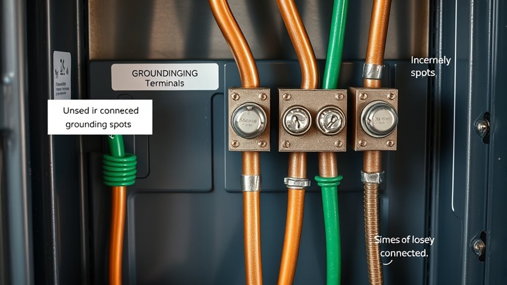
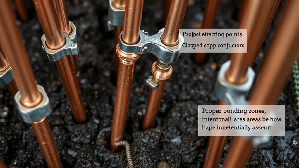
Primary Building Grounding Attachment Points
Primary building grounding attachment points are critical for ensuring a reliable and low-impedance path to earth. When you connect structural steel or the building frame, make sure it’s permanently and electrically continuous. This provides an acceptable electrode and a common attachment point, reducing resistance during fault conditions. Attach bonding conductors at the closest accessible point to the main grounding conductor to minimize impedance and facilitate fault current flow. Use accessible hardware and terminations that allow inspection and maintenance; avoid concealed welds without accessible bonding points. If the structure has multiple large sections, like separate legs, you may need multiple bonding points to maintain an equipotential grid. Proper attachment guarantees safety, system performance, and compliance with electrical codes. Additionally, ensuring that connections are free of corrosion and mechanical damage helps maintain a low-resistance path over time. Regular inspections and proper maintenance of the grounding system are essential to sustain low resistance and reliable operation. Incorporating corrosion-resistant materials in grounding connections can further enhance longevity and safety. Ensuring proper connection torque is also vital to prevent loosening over time, which can compromise the grounding integrity. Implementing proper installation practices can help prevent future issues and ensure long-term system reliability.
Acceptable Grounding Connections for Electrical Systems

When establishing grounding connections, you need to guarantee they’re approved and reliable. Using listed connectors, clamps, or approved welding methods helps maintain low-resistance paths. Properly verified grounding points ensure safety and compliance with electrical codes. Proper installation practices are essential to prevent future issues and ensure the system’s effective operation. Additionally, selecting approved grounding methods according to electrical standards ensures long-term system stability and safety. Incorporating natural pool design principles can also support sustainable and environmentally friendly backyard setups. Ensuring proper sound quality and levels during installation can further enhance system performance and safety. Regular inspection and adherence to electrical safety guidelines can help mitigate potential hazards and maintain system integrity over time. Incorporating grounding system testing methods is also recommended to verify that all connections function correctly and safely.
Approved Connection Methods
Approved connection methods guarantee a secure, low-resistance bond between grounding electrodes and conductors, which is essential for system safety and performance. Using exothermic (cadweld) welding provides a permanent, reliable connection listed in NEC 250. Grounding conductors can also be attached with listed lugs and clamps rated for electrode material and burial conditions. Approved pressure connectors and compression fittings, when installed per manufacturer instructions, are acceptable. For interconnecting electrodes, a copper bonding jumper sized according to NEC tables and routed to avoid damage is required. Mechanical bolted or threaded connections are permitted only if listed for the application and protected against corrosion. Always verify the connection methods meet code requirements to maintain system integrity and safety. Proper installation ensures the long-term reliability of grounding systems and reduces the risk of potential differences that could cause electrical hazards. Additionally, adhering to recognized grounding practices supported by industry standards helps ensure compliance and safety over time. Properly installed connections can also help prevent corrosion, which could compromise system effectiveness. Incorporating proper tightening techniques is crucial to prevent loose connections that might lead to increased resistance and potential failure. Furthermore, using quality materials that meet industry standards can significantly improve the durability of grounding connections.
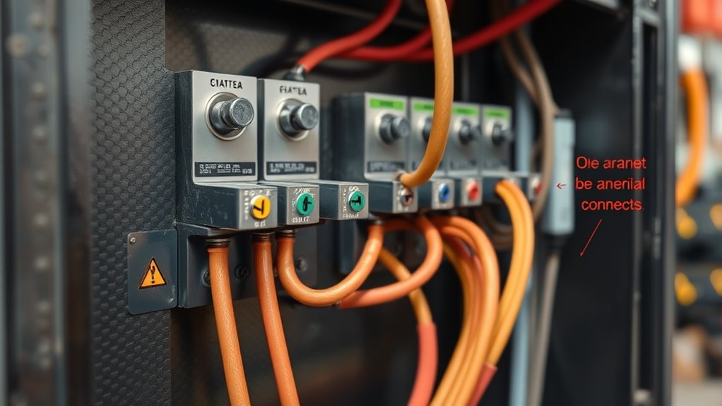
Verified Grounding Points
Verified grounding points guarantee that electrical systems maintain a low-resistance, dependable connection to earth, which is essential for safety and system performance. Common acceptable grounding electrodes include driven ground rods, buried copper conductors, structural steel, metal water piping, and concrete-encased electrodes. For industrial applications, verified plant grounding points are designated network nodes, bonding points with visual indicators, central grounding busbars, substation grounds, and lightning/discharge points tested for low impedance. Equipment chassis and frames should connect directly to building grounding conductors, bonding enclosures securely, and using verified clamps. Avoid unsafe connections—such as isolated metallic systems, neutral bonds, or corroded surfaces. Proper confirmation ensures reliable, code-compliant grounding, preventing hazards and system failures. Additionally, following environmental considerations helps maintain sustainable and safe grounding practices. Ensuring that grounding connections are regularly inspected and tested aligns with best practices for grounding system reliability and reduces the risk of system malfunctions. Verifying grounding connection quality with appropriate testing equipment further enhances system dependability and safety.
Grounding Points to Avoid for Safety and Compliance
To guarantee safety and compliance, avoid attaching grounding conductors to nonconductive structures like wood framing, drywall, plastic, or fiberglass, since these materials can’t carry fault current reliably. These surfaces are insulating and won’t provide a proper low-resistance path to earth, increasing shock and fire risks if used as a ground. Painted or corroded metal surfaces can have high contact resistance, leading to discontinuous grounding and violating bonding rules. Do not use equipment enclosures or panel covers that are isolated or floating as the sole ground points because they may lack continuity to system ground. Additionally, avoid attaching grounding conductors to temporary supports like scaffolding or ladders, which are often nonbonded or intermittently bonded, creating false safety assurances and risking regulatory violations. Regular inspections of grounding connections are essential to ensure ongoing compliance and safety in electrical systems. It is also important to understand the grounding system to prevent improper connections and ensure reliable safety performance. Proper grounding practices help in maintaining electrical safety and avoiding hazards, especially in environments with complex electrical setups.
Verifying and Testing Grounding Locations Effectively
Effective verification and testing of grounding locations are essential to guarantee safety and compliance. Use methods like the Wenner 4-Pin or Schlumberger 4-Pin to accurately measure resistance and resistivity, especially for large or complex systems. The Wenner method is preferred for its accuracy, with electrodes driven in a straight line at equal distances, measuring voltage between inner probes and current between outer probes. The Schlumberger method offers higher sensitivity for larger spacing, adjusting electrode placement accordingly. For remote or new installations, the Fall-of-Potential 3-Point method provides reliable results by measuring voltage between the ground electrode and a remote probe. In urban areas, the Clamp method allows selective testing without disconnection. Always verify proper probe placement and follow standardized procedures for dependable results. Adhering to IEEE standards ensures that testing procedures are consistent and reliable across different environments. Additionally, understanding ground resistance and its impact on safety is crucial for proper system evaluation. Proper testing procedures also help in ground system safety, which is vital for protecting both equipment and personnel. Proper testing involves verifying that the testing instruments are calibrated correctly to ensure accurate readings and prevent false assessments. Conducting regular testing is also important to maintain system integrity over time.
Material and Sizing Guidelines for Grounding Conductors
Selecting the appropriate material and size for grounding conductors is essential to guarantee safety, reliability, and code compliance. Copper, either bare or insulated, is the preferred choice due to its high conductivity, excellent thermal performance, and flexibility for mechanical connections. Copper-clad steel offers added strength and corrosion resistance, suitable where mechanical durability is needed. Galvanized steel is less common because of its lower conductivity and susceptibility to corrosion, making it less reliable for grounding. Aluminum and ACSR are generally poor choices for grounding because of lower conductivity and melting points. When sizing conductors, follow NEC Table 250.66, considering material-specific adjustments to ensure sufficient fault current capacity. Always verify local codes, which may specify minimum sizes, and ensure conductors can withstand thermal stresses during faults. Proper grounding conductor standards and proper system design are vital for ensuring an effective grounding system that maintains safety during fault conditions. Additionally, understanding the grounding system components helps ensure compliance with safety regulations and can prevent costly failures and enhance overall safety. It is also important to consider the installation environment to select the most appropriate conductor type and size for longevity and safety.
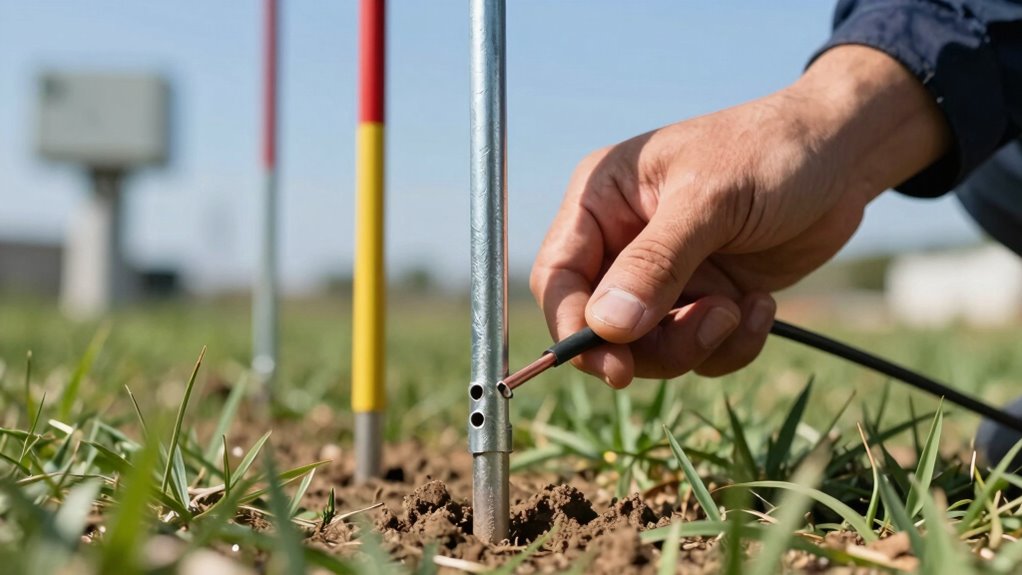
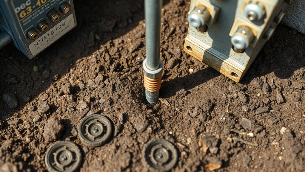
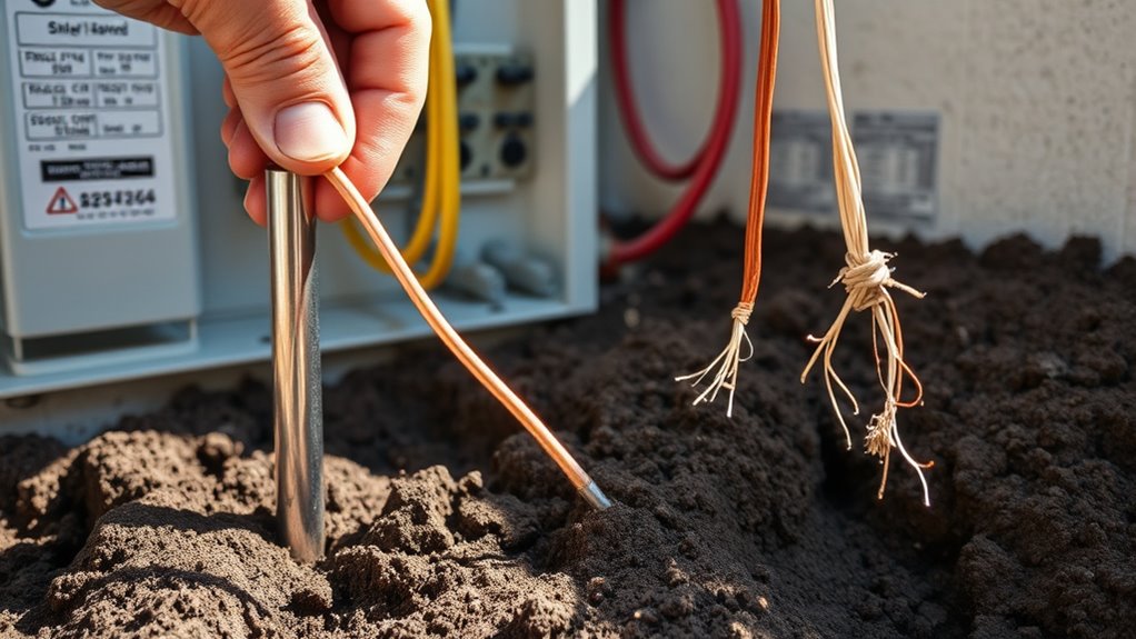
Proper Installation Techniques for Grounding Electrodes
Proper installation of grounding electrodes begins with careful site selection and adherence to spacing requirements. You should guarantee vertical rod electrodes are at least 8 feet deep unless bedrock prevents it, to maximize soil contact and reduce resistance. When installing multiple rods, space them at least equal to the rod length—often twice—to minimize overlapping influence zones and improve effectiveness. If a code-supplemental rod is needed, place it at least 6 feet from the first. Avoid underground utilities, foundations, pavement, and large rocks to prevent damage and ensure proper depth. Install electrodes in moist, stable soil and below the frost line to maintain consistent resistance. Use approved connection methods like exothermic welding or listed clamps, and ensure proper bonding practices to secure reliable grounding. Additionally, using low-resistance materials and ensuring firm contact with surrounding earth can significantly enhance the overall grounding system’s effectiveness. Incorporating grounding system testing and regular inspections ensures continued safety and performance of your electrical grounding setup.
Protecting and Maintaining Grounding Systems Over Time
To guarantee your grounding system remains dependable over time, regular inspection and testing are essential. Conduct visual inspections quarterly or annually, checking for damage, corrosion, and proper seating of components, using non-invasive methods like specialized cameras for safety. Verify connections for pitting, erosion, or high resistance. Measure ground resistance annually with a ground resistance meter, comparing results to past data. Test continuity and insulation resistance before maintenance. Address corrosion promptly by inspecting connections, applying protective coatings, and monitoring soil conditions like pH and moisture. Keep cables and clamps clean, tighten loose connections, and replace worn parts swiftly. Follow scheduled maintenance, document all inspections and repairs, and update records regularly. Proper upkeep minimizes downtime and ensures your grounding system remains effective and safe over its lifespan.
Bonding Multiple Grounding Electrodes and Systems
When bonding multiple grounding electrodes and systems, you need to ensure low-resistance connections to maintain effective grounding. Proper spacing and sizing of bonds are vital to prevent issues and meet code requirements. By focusing on these points, you help create a reliable and compliant grounding system. Metal underground water pipes, for example, must meet specific contact and bonding conditions to serve as a grounding electrode, emphasizing the importance of proper connection techniques.
Ensuring Low-Resistance Bonds
Ensuring low-resistance bonds between grounding electrodes and systems is essential for effective electrical safety. You should bond all electrodes at a building to form a single system, following NEC 250.52(A). Metal support structures in contact for 10 feet or more can be bonded together, with one electrode permitted if multiple are present. Using a bare copper conductor no smaller than 4 AWG helps maintain a low-resistance bond. You can also bond grounding conductors to existing electrodes like water pipes or building frames. Industry standards recommend a resistance of 5 ohms or less for large systems, though NEC allows up to 25 ohms. Post-installation testing guarantees resistance stays low, preventing voltage potential issues and ensuring reliable grounding performance. Proper bonding minimizes resistance and enhances electrical safety. Proper installation practices are crucial to ensure the longevity and effectiveness of grounding systems.
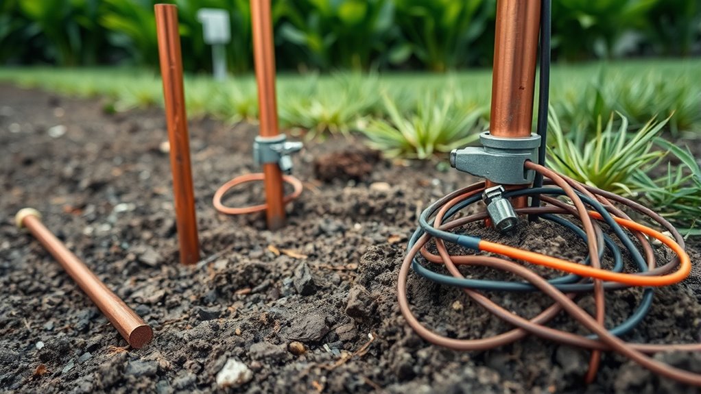
Proper Spacing and Sizing
Proper spacing and sizing of grounding electrodes are essential for effective system performance and safety. To guarantee optimal results, follow these key points:
- Maintain a minimum separation of 6 ft (1.83 m) between electrodes on different systems, but consider doubling rod length to reduce mutual influence.
- Use longer rods (e.g., 10 ft) installed below frost lines in cold climates for better performance.
- Bond electrodes with conductors sized per NEC Table 250.66, typically 8 AWG copper for residential, larger if load requires.
- Connect multiple electrodes with conductors that match or exceed the size of main grounding conductors to handle fault currents.
- When space is limited, bond electrodes to avoid isolation, but aim for adequate separation to minimize overlapping influence zones.
- Placing grounding rods close to the panel is generally preferred for practicality and effectiveness, as it simplifies connections and improves grounding performance.
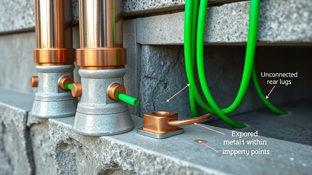
Common Mistakes That Lead to Grounding Failures
Many grounding failures stem from simple mistakes during installation or maintenance. You might leave metal enclosures or appliance chassis unconnected to the grounding conductor, exposing metal parts that can energize during faults. Using short jumper links from the grounding screw to neutral instead of a proper grounding conductor creates dangerous bonded neutral paths, risking shock and fire. Loose clamps or terminal connections can open the ground path over time due to vibration or thermal cycles, leading to intermittent grounding issues. Reusing corroded or unlisted clamps at electrode or conductor terminations increases resistance and weakens fault clearance. Forgetting to reattach grounding conductors after relocating equipment leaves circuits ungrounded, making them unsafe. These mistakes compromise the low-impedance fault path essential for safety and proper system operation. Proper grounding practices are crucial for maintaining system safety and preventing electrical hazards.
Ensuring Code Compliance in Grounding Practices
To guarantee your grounding practices meet code, you need to verify you’re using proper grounding points and approved components. Regularly maintain and test your system to catch any issues early and keep it compliant. Following these steps helps prevent grounding failures and ensures safety. Proper grounding also depends on correct installation techniques, such as driving ground rods to the proper depth and securing all connections tightly to ensure system safety.
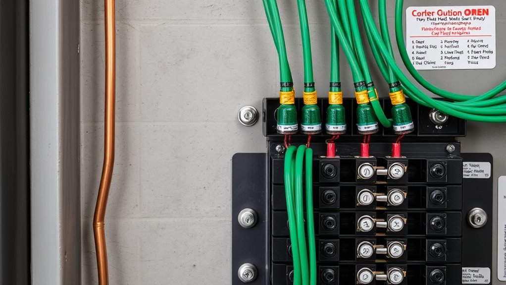
Verify Proper Grounding Points
Ensuring grounding points meet code requirements is essential to maintain system safety and reliability. You need to verify that ground rods are installed at the correct depth—at least 8 feet—and properly spaced. Confirm the grounding electrode conductor (GEC) is securely clamped, correctly sized (usually #6 or #4 AWG copper wire), and free from damage. Check that the main panel’s neutral and ground are bonded only in the main service panel, while subpanels have these isolated. Inspect all connections to ensure they’re tight and corrosion-free. Additionally, confirm that bonding is established on metal water and gas pipes when applicable. Proper inspection helps prevent faults and guarantees compliance with NEC standards, safeguarding both people and equipment.
Use Approved Components Only
Why is it essential to use only approved grounding components? Using approved components guarantees your grounding system meets safety and code standards, reducing risks of electrical faults and fires. The NEC specifies standards for grounding electrodes, such as minimum lengths and materials like galvanized steel or copper. Approved components like grounding conductors, bars, and clamps undergo UL 467 certification, confirming they resist corrosion, UV, moisture, and extreme temperatures. Properly rated and listed parts guarantee reliable connections and electrical conductivity, preventing failures. For example, grounding rods must be at least 8 feet long, and clamps must be secure and certified. UL certification ensures the components are tested for durability and safety, and by sticking to approved components, you ensure your system’s integrity, pass inspections, and stay compliant with all electrical safety regulations.
Maintain and Test Regularly
Regular maintenance and testing are essential to keep your grounding system reliable and compliant with electrical codes. By performing routine inspections, you can identify wear, corrosion, loose connections, or mechanical damage before they cause failures. Regular cleaning ensures that corrosion doesn’t hinder conductivity, while tightening connections prevents resistance increases. Ground resistance testing verifies that your system meets standards like 25 Ω or less, ensuring proper fault current clearance. Keep detailed records of all tests, repairs, and inspections to track performance over time. Schedule these activities periodically and after any maintenance or environmental changes. Routine testing helps detect potential issues early and prolongs the lifespan of grounding components, reducing the risk of electrical faults or equipment failure.
- Examine conductors, connectors, and electrodes for damage
- Remove corrosion from grounding components
- Tighten and clean connections regularly
- Test grounding resistance annually or as needed
- Document all inspections and test results
Frequently Asked Questions
How Do I Determine the Best Grounding Point in My Building?
You determine the best grounding point by identifying the building’s steel or main equipment grounding busbar, guaranteeing it’s connected to a low-resistance path—ideally under 10Ω. Check soil conditions, choosing areas with low resistivity like wet or clay soil. Avoid power or lightning grounds, and ensure the connection is continuous, corrosion-free, and properly bonded. Use deep or chemically treated rods if soil resistance is high to maintain safety and effectiveness.
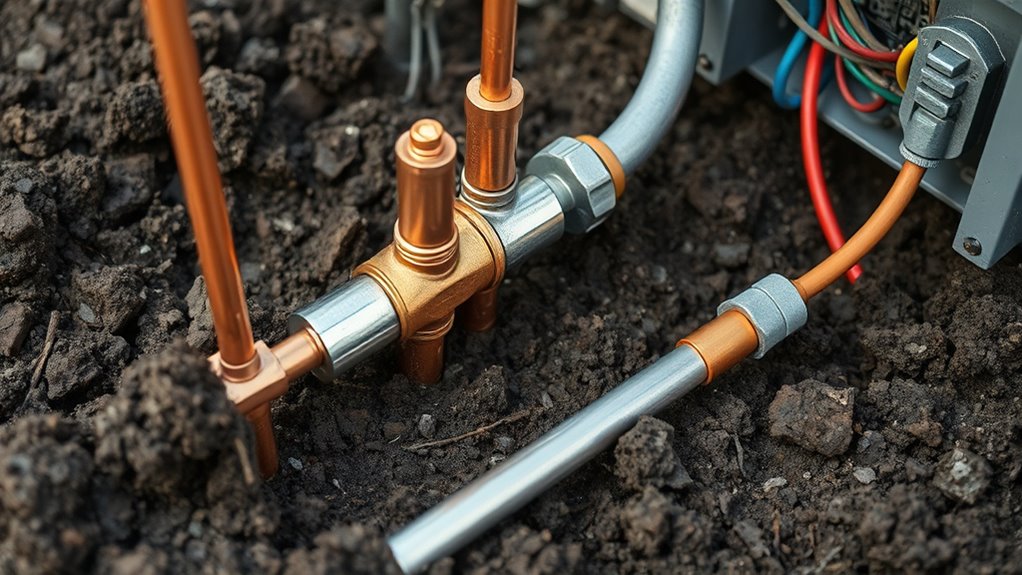
Can Plumbing Be Used as a Reliable Grounding Electrode?
Imagine a metal pipe running underground, connecting to the earth like roots of a tree. Yes, plumbing can serve as a grounding electrode if it’s properly installed—at least 8 feet long, in contact with the earth, and made of corrosion-resistant material. But remember, it must be continuous, accessible, and supplemented if resistance exceeds 25 ohms. Otherwise, relying solely on plumbing might compromise safety.
What Testing Methods Confirm a Proper Grounding Connection?
You can verify a proper grounding connection through continuity and low-resistance tests. Use ground bond or continuity testers to inject high DC currents and measure voltage drops, ensuring low impedance (milliohms). Also, perform ground grid integrity tests to confirm the conductor’s continuity without excavation. Make sure to visually inspect clamps and connections, and follow standards like IEEE to ensure your grounding system is reliable and safe.
How Often Should Grounding Systems Be Inspected and Retested?
You might think your grounding system’s fine if it’s never been tested, but standards actually recommend inspections every 3-5 years, more often if you notice issues like flickering lights or surges. For older homes, every 2-3 years is prudent. Regular testing isn’t just a suggestion; it’s essential for safety. Don’t wait for a shock—schedule your inspections and retests now to keep everything grounded and safe.
What Are the Hazards of Improper Grounding Attachment Points?
If you attach grounding points improperly, you risk electric shock, fire, and equipment damage. Fault currents may take unintended paths through metal parts or water, increasing shock hazards. Poor grounding can cause arcing, overheating, and circuit failures, leading to fires or equipment malfunctions. It also creates electrical noise and data errors in systems, plus violates safety codes. Always guarantee grounding is correctly connected to prevent these serious hazards.
Conclusion
Proper grounding is essential for safety and system reliability. Did you know that improper grounding causes over 50% of electrical failures? By understanding where to attach and where to avoid, you can prevent hazards and ensure code compliance. Regularly verify your grounding points and maintain your system. Staying informed helps protect your property and loved ones. Take these practices seriously—your safety depends on it.